Every safe voyage rests on an invisible balance struck before the ship ever leaves the berth. A vessel floats because the water pushes up on its hull with a force equal to its weight, but floating is not the same as being safe — the real question is what happens when a wave, a gust, a turn or a shift of cargo pushes the ship over. Does it swing back upright, or does it keep going? That behaviour is stability, and it is governed by a handful of geometric relationships between three points inside every ship: its centre of gravity, its centre of buoyancy, and a point called the metacentre. Get the relationship between them right and the ship rights itself from any reasonable heel; get it wrong and the vessel can loll, capsize, or fail to survive flooding that a well-loaded ship would shrug off. For the officers who load and operate ships, stability is not abstract naval architecture — it is a daily calculation with hard regulatory limits, done for every loading condition before departure. This guide explains the principles from the ground up: the three points and the geometry that connects them, metacentric height and what it tells you, the righting-arm curve and the intact stability criteria a ship must pass, the free surface effect that quietly erodes stability, damage stability and how modern rules measure survivability, and the practical tools and habits that keep a ship inside its limits. To keep stability documentation, loading conditions and the checks behind every departure organised across your fleet, start a free trial or book a demo.
INDUSTRY GUIDE · NAVAL ARCHITECTURE
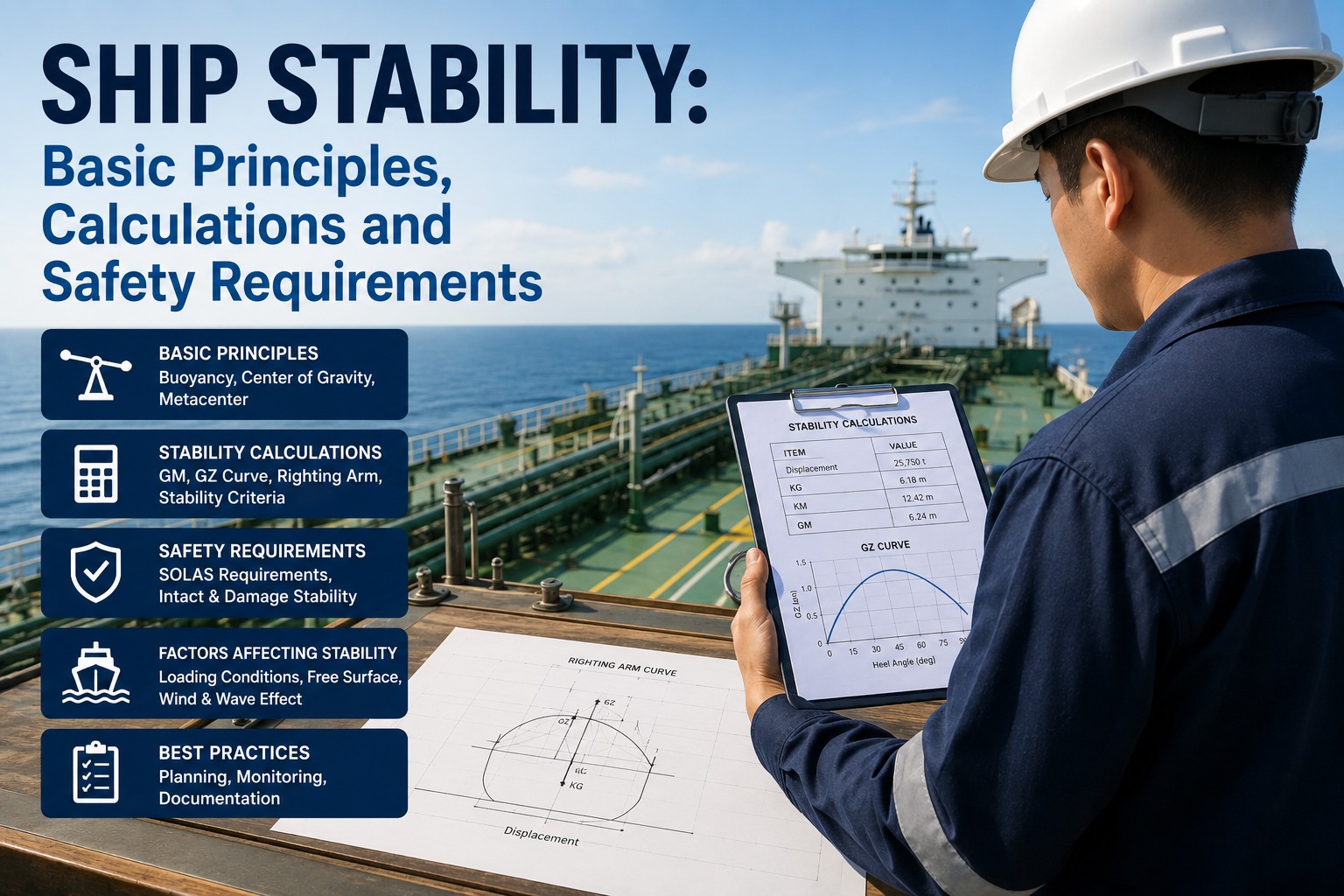
Ship Stability: Basic Principles, Calculations and Safety Requirements
An educational guide for deck officers and superintendents to the geometry that keeps a ship upright — the centres of gravity, buoyancy and the metacentre, metacentric height and the GZ curve, the intact stability criteria, free surface effect, damage stability, and the practical loading checks behind every safe departure.
1. The Three Points That Decide Everything
All of ship stability comes down to the interaction of three points inside the hull, and once these are clear the rest of the subject follows logically rather than as a set of formulas to memorise. Two forces act on a floating ship — its weight pulling down, and the buoyancy of the displaced water pushing up — and the three points describe where those forces act and how their relationship changes as the ship heels.
POINT G
Centre of gravity
The point through which the total weight of the ship and everything in it acts downward. Its height above the keel is KG. Loading cargo high raises G; loading low or adding ballast in the bottom lowers it. G moves whenever weight is added, removed or shifted, and controlling its height is the single most important thing an officer does for stability.
POINT B
Centre of buoyancy
The centre of the underwater volume — the point through which the upward buoyant force acts. Its height above the keel is KB. As the ship heels, the shape of the underwater volume changes and B moves toward the low side, which is precisely what generates the force that rights the ship or fails to.
POINT M
The metacentre
The point where the vertical line of buoyant force, at a small angle of heel, crosses the ship's centreline. Its height above the keel is KM, and it is found from KM = KB + BM, where BM is the metacentric radius set by the hull's waterplane shape. For small angles M stays effectively fixed, which is what makes it so useful.
The whole of initial stability is captured in how G sits relative to M. When the ship heels, B moves out to the low side and the buoyant force, acting upward through the new B, no longer lines up with the weight acting down through G. The horizontal separation between these two forces creates a couple — a turning moment. If M is above G, that couple pushes the ship back upright; if M is below G, the couple pushes it further over. Everything else in this guide is an elaboration of that one idea: keep the metacentre above the centre of gravity, by enough margin, through every angle that matters.
2. Metacentric Height — the Measure of Initial Stability
The distance between the centre of gravity and the metacentre is the metacentric height, GM, and it is the single most quoted number in ship stability. It is calculated simply, from the two heights above the keel: GM = KM − KG. Because KM comes from the ship's hull form and hydrostatics for a given draft, and KG comes from how the ship is loaded, GM ties the fixed geometry of the hull to the variable reality of the cargo.
GM is the best measure of initial stability — the ship's behaviour at small angles of heel, up to roughly ten degrees. A positive GM means the metacentre is above the centre of gravity, the ship has a restoring moment, and it will return upright from a small heel. The size of GM sets the initial slope of the whole stability curve, so a larger GM means larger righting arms at small angles. But bigger is not simply better, and understanding why is what separates a rote answer from real judgement.
LARGE GM
A "stiff" ship
Large righting arms develop even at small angles, so the ship resists heeling hard and snaps back upright quickly. It sounds safe, but that violent, rapid roll strains the hull, can shift and damage cargo, injure crew and stress lashings. A very stiff ship is uncomfortable and hard on everything aboard.
vs
SMALL GM
A "tender" ship
Small righting arms mean the ship rolls slowly with a long, easy period. It feels comfortable, but it leaves little margin against unexpected loads, and if GM falls too far it approaches the point where the ship no longer reliably returns upright. Tender is easy until it is dangerous.
Good stability is a compromise between the two, so the ship rolls easily without generating excessive stresses and without running short of margin. Typical target GM varies by ship type and loading — general cargo ships often aim for roughly half a metre to a little over a metre, container ships sometimes lower to soften roll accelerations, and tankers and bulk carriers span a wider band depending on the condition. Underneath all of them sits a hard floor: the IMO Intact Stability Code sets a minimum GM of 0.15 metres for most vessels, and no compliant departure condition may fall below it.
i
Positive GM is necessary, not sufficient
A common and dangerous misconception is that a positive GM proves a ship is safe. It does not. GM only describes the initial slope of the stability curve at small angles — it says nothing about how the ship behaves at thirty, forty or fifty degrees of heel, where hull form takes over. A ship can have a perfectly healthy GM and still fail the large-angle criteria that determine whether it survives a real heeling event. This is exactly why the full stability booklet, and the complete righting-arm curve, must be checked before departure rather than relying on a single reassuring number.
3. The Righting-Arm (GZ) Curve
Where GM describes small angles, the righting-arm curve describes the whole story. As a ship heels beyond about ten degrees, the metacentre no longer stays fixed and the simple GM relationship breaks down, so stability at larger angles is described by the righting arm, GZ — the horizontal distance between the upward buoyant force and the downward weight at each angle of heel. Plotted against heel angle, GZ forms the curve of static stability, and reading it is the core skill of stability assessment.
Initial slope
The slope of the GZ curve at zero heel equals the metacentric height, so GM and the curve are directly linked — GM is simply where the curve begins. This is why the two are not competing descriptions but the same physics at different scales.
Maximum righting arm
The peak of the curve, and the angle at which it occurs, characterise the ship's resistance to large heel. A higher peak occurring at a larger angle means more reserve against being pushed over by wind, waves or a heeling moment.
Area under the curve
The area under the GZ curve is the dynamic stability — the energy required to heel the ship to a given angle. This matters because real heeling events are about energy, not just a static push: a gust or a wave delivers energy, and the area is what absorbs it.
Angle of vanishing stability
The angle at which GZ returns to zero and the ship can no longer right itself. Beyond this point the righting arm becomes negative and the ship will capsize. It defines the outer limit of survivable heel for the loading condition.
Together these features give a complete graphical description of a vessel's stability at a given displacement and loading. Two ships with identical GM can have very different GZ curves — different peaks, different vanishing angles, different areas — because hull form governs how GZ develops once the ship heels past the initial range. This is the deep reason the curve, not the single number, is the object the regulations actually test.
Keep every loading condition's stability checks on the record
Stability is calculated fresh for every departure condition, and the evidence that each one passed is exactly what class, port state control and a charterer may ask to see. Marine Inspection keeps stability documentation, loading conditions and the pre-departure checks organised per vessel, with the trail auditable across the fleet. See how it keeps the paperwork behind safe loading in order.
4. The Intact Stability Criteria
The regulations turn the GZ curve into a set of pass-or-fail tests. The 2008 International Code on Intact Stability — adopted by IMO Resolution MSC.267(85) on 4 December 2008 and in force from 1 July 2010 — is made mandatory through SOLAS Chapter II-1 and the Load Line Protocol, and it sets the criteria every compliant loading condition must meet. These are the numbers an officer checks against for each condition before departure.
0.15 m
Minimum metacentric height
The corrected initial GM must be at least 0.15 metres — the floor below which initial stability is considered inadequate.
0.20 m
Minimum righting arm at 30°
GZ must be at least 0.20 metres at a heel angle of 30 degrees or more, ensuring meaningful righting capacity at a substantial angle.
≥ 25°
Angle of maximum GZ
The maximum righting arm should occur at a heel angle of 25 degrees or more, so peak stability is not reached too early.
0.055
Area 0° to 30° (m·rad)
The area under the GZ curve up to 30 degrees must be at least 0.055 metre-radians of dynamic stability.
0.090
Area 0° to 40° (m·rad)
The area up to 40 degrees, or the downflooding angle if that is less, must be at least 0.090 metre-radians.
0.030
Area 30° to 40° (m·rad)
The area between 30 and 40 degrees, or to the downflooding angle if less, must be at least 0.030 metre-radians.
Beyond these general criteria, the Code includes the weather criterion, which tests the ship's ability to withstand the combined heeling of a severe beam wind and rolling: in essence, the ratio of the ship's righting capacity to the heeling energy from wind and waves must show sufficient reserve. A loading condition is only acceptable when it satisfies all of these together, which is why a ship with an ample GM can still be non-compliant if its curve falls short on area or peak angle. The downflooding angle — the heel at which water would begin entering through non-weathertight openings — caps several of these measures, because stability that depends on angles the ship cannot safely reach without flooding is stability that cannot be counted.
5. The Free Surface Effect
One of the most important and least intuitive threats to stability comes not from cargo but from liquid in partially filled tanks. When a tank is slack — neither full nor empty — the liquid inside is free to move as the ship heels, and it flows to the low side. That shift of weight to the low side acts exactly like raising the ship's centre of gravity, reducing the effective GM. This is the free surface effect, and it is why stability calculations always use a GM corrected for free surfaces rather than the raw solid figure.
i
The counterintuitive part every officer must know
The free surface penalty depends on the breadth of the liquid surface in the tank, not on how much liquid is present. This has a startling consequence: a tank one-tenth full and a tank nine-tenths full carry the same free-surface moment, because both have the same free surface area. A nearly full tank is just as damaging to stability as a nearly empty one. This is why the standard operational defence is to keep tanks either pressed fully up or completely empty wherever possible, minimising the number of slack tanks — and why a ship can lose its required GM margin simply by having too many tanks partly filled, even when its solid-condition GM looked comfortable.
The practical discipline that follows is straightforward but essential: minimise slack tanks, and always work with the corrected GM. A loading computer or the stability booklet applies the free-surface correction automatically, but the officer has to understand what it is doing, because the temptation to leave several tanks slack for operational convenience is exactly how a compliant-looking condition quietly slips below its limits. Free surface is invisible on deck and decisive on the curve.
6. Negative GM and the Angle of Loll
The most dangerous stability condition is a negative GM, where the centre of gravity has risen above the metacentre. Here the couple that forms when the ship heels acts in the direction of the heel rather than against it — the upright position is unstable, and the smallest disturbance makes the ship fall away from vertical rather than return to it. This is a critical emergency, and recognising it is a matter of safety, not theory.
A ship with negative initial GM does not always capsize immediately, and understanding why is important. As it heels, hull form can move the centre of buoyancy far enough that, at some larger angle, a new equilibrium forms where the righting arm returns to zero. The ship then settles at that angle — the angle of loll — lolling to one side, neither upright nor capsized, but in a precarious state from which a wave or a gust to the low side can be fatal. A ship at an angle of loll is not simply listing; it is sitting at the edge of its remaining stability.
Loll is not list — and the correction differs
An angle of loll can look like an ordinary list, but its cause and its cure are opposite, and getting them confused can capsize the ship. A list comes from an off-centre weight and is corrected by addressing that weight. A loll comes from negative GM — too high a centre of gravity — and the correct response is to lower G: add ballast low in the vessel, starting with tanks on the low side to avoid a violent lurch as the ship flops through upright, and remove or lower topside weight. Adding weight high, or ballasting the high side first, can make matters catastrophically worse. Because the two look alike but demand opposite actions, correctly diagnosing loll versus list is one of the most important judgements in practical stability.
Give every officer the same current stability information
Sound stability decisions depend on everyone working from the current stability booklet, the right loading limits and a clear record of the vessel's condition. Marine Inspection keeps stability documentation and loading records current and accessible per vessel, so the information behind a loading decision is the latest version, not a dog-eared copy. See how it keeps critical documentation in one place.
7. Damage Stability — Surviving Flooding
Everything so far concerns the intact ship. Damage stability asks a harder question: if the hull is breached and a compartment floods, will the ship survive, or will progressive flooding and loss of stability sink or capsize it? This is governed by the ship's watertight subdivision — the arrangement of watertight bulkheads that limit how far flooding can spread — and by a set of modern rules that measure survivability probabilistically.
The harmonised SOLAS regulations in Chapter II-1, applying to dry cargo ships of eighty metres and above and to all passenger ships from a keel-laying date on or after 1 January 2009, use the probability of survival after damage as the measure of safety. Rather than testing a single assumed damage, the probabilistic method considers the whole range of possible damages and weights each by how likely it is.
A
Attained subdivision index
A measure of the ship's actual survivability, calculated as A = Σ pᵢsᵢ — the sum, over all considered damage cases, of the probability pᵢ that a given compartment or group floods, multiplied by the probability sᵢ that the ship survives that particular flooding. It is, in effect, the overall probability that the ship survives a random collision and flooding event.
R
Required subdivision index
The minimum acceptable level of survivability, a function of ship length and, for passenger ships, the number of persons aboard. It represents the standard society deems acceptable for collision and flooding. Compliance is simply the requirement that A is not less than R.
The elegance of the approach is that it rewards good subdivision directly: a ship with more and better-placed watertight compartments floods less extensively and survives more damage cases, raising its attained index A. The factor pᵢ depends only on the watertight arrangement, while sᵢ depends on the ship's shape and the loading condition, so both design and operation feed the result. Supporting this, SOLAS requires a damage control plan and damage control booklet giving officers clear information on the watertight subdivision, so that in a real flooding event they can act quickly to prevent progressive flooding through openings and preserve what stability remains. Damage stability is where naval architecture and emergency seamanship meet.
8. Stability in Practice — the Officer's Daily Discipline
The principles become safety only through the routine that applies them. On a working ship, stability is assessed for every loading condition before departure, and a set of tools and habits turns the theory into a daily check that keeps the vessel inside its limits.
TOOL
The trim and stability booklet
Every ship carries an approved booklet of its hydrostatic data and standard loading conditions, each shown to comply with the criteria. It is the reference against which any proposed condition is judged, and checking a loading against the booklet is the baseline stability discipline before departure.
TOOL
The loading computer
An approved onboard computer builds the GZ curve, applies the free-surface correction, and checks the condition against the IMO criteria for the actual planned load — the master and chief officer's practical instrument for verifying that a specific departure condition passes before the cargo is fixed.
TOOL
The inclining experiment
Carried out on the completed ship, this measured test establishes the lightship KG and displacement that all subsequent stability calculations depend on. Done in calm water at design trim with no loll, it anchors the whole stability model to the real vessel rather than the design drawings.
Around these tools sits the judgement that no computer replaces. The officer plans the load to keep the centre of gravity low and the GM within a sensible band — comfortable rather than stiff, safe rather than tender — minimises slack tanks to control free surface, accounts for how the condition will change as fuel and stores are consumed and ballast adjusted during the voyage, and watches for the warning signs of a sluggish or lurching roll that betrays a stability problem the numbers may not yet show. Consumption during a voyage matters because a ship that departs compliant can drift toward the margins as low fuel and stores are burned off and the centre of gravity rises, so the worst condition is not always the departure condition. Stability is a living property of the ship, recalculated as the loading changes, and the discipline of treating it that way — every condition, every departure, corrected for free surface, checked against the full criteria — is what keeps ships upright. The geometry is fixed and elegant; the safety comes from applying it faithfully, every single time. To keep the stability booklets, loading records and pre-departure documentation behind that discipline organised and current across your fleet, start a free trial or book a demo.
Frequently Asked Questions
What is metacentric height (GM) and why does it matter?
GM is the vertical distance between a ship's centre of gravity and its metacentre, calculated as GM = KM − KG. It is the best measure of initial stability — the ship's behaviour at small angles of heel up to about ten degrees. A positive GM means the ship has a restoring moment and returns upright from a small heel; the size of GM sets the initial slope of the whole stability curve. The IMO Intact Stability Code sets a minimum GM of 0.15 metres for most vessels, so no compliant loading condition may fall below it.
What is the difference between GM and the GZ curve?
GM is a single number describing initial stability at small angles, while GZ is the righting arm at each angle of heel, plotted as a curve that describes stability across the full range. The slope of the GZ curve at zero heel equals GM, so they are linked, but the curve reveals what GM cannot: the maximum righting arm and the angle it occurs at, the area under the curve (the energy needed to heel the ship), and the angle of vanishing stability beyond which the ship capsizes. Two ships with the same GM can have very different GZ curves because hull form governs stability at larger angles.
Does a positive GM mean a ship is safe?
No. A positive GM only establishes that the initial slope of the stability curve is positive — the ship returns upright from small angles. It says nothing about behaviour at thirty, forty or fifty degrees, where hull form takes over and the intact stability criteria actually apply. A ship can have a healthy GM yet still fail the criteria for righting arm, area under the curve or angle of maximum GZ. This is why the full stability booklet and the complete GZ curve must be checked for every loading condition before departure, rather than relying on a single GM value.
What are the main IMO intact stability criteria?
Under the 2008 Intact Stability Code, a loading condition must meet all of the following: a corrected GM of at least 0.15 metres; a righting arm (GZ) of at least 0.20 metres at 30 degrees or more; the maximum GZ occurring at 25 degrees or more; area under the GZ curve of at least 0.055 metre-radians up to 30 degrees, at least 0.090 up to 40 degrees or the downflooding angle, and at least 0.030 between 30 and 40 degrees; plus the weather criterion for severe wind and rolling. All must be satisfied together, so an ample GM alone does not guarantee compliance.
What is the free surface effect?
It is the loss of effective stability caused by liquid moving in a partially filled tank. As the ship heels, the free liquid flows to the low side, and that shift acts like raising the centre of gravity, reducing the effective GM. Crucially, the penalty depends on the breadth of the liquid surface, not the amount of liquid — so a tank one-tenth full and one nine-tenths full carry the same free-surface moment. The defence is to keep tanks pressed full or empty and minimise slack tanks, and always to work with the free-surface-corrected GM rather than the solid figure.
What is an angle of loll and how is it corrected?
An angle of loll occurs when a ship has negative GM — its centre of gravity has risen above the metacentre, making the upright position unstable. Rather than capsizing immediately, hull form may create a new equilibrium at some larger angle, and the ship settles there, lolling to one side in a precarious state. It looks like a list but has the opposite cause and cure: a loll is corrected by lowering the centre of gravity — adding ballast low, starting on the low side, and removing topside weight — whereas adding weight high or ballasting the high side first can capsize the ship. Diagnosing loll versus list correctly is critical.
What is damage stability and how is it measured?
Damage stability is the ship's ability to survive flooding after the hull is breached, governed by its watertight subdivision. Modern SOLAS rules use a probabilistic method for dry cargo ships of eighty metres and above and all passenger ships built from 1 January 2009. It compares an attained subdivision index A — calculated as A = Σ pᵢsᵢ, summing the probability of each flooding case by the probability of surviving it — against a required index R that depends on ship length and passenger numbers. The ship complies when A is not less than R, so better watertight subdivision directly raises survivability.
What tools does an officer use to check stability?
Three principal tools. The approved trim and stability booklet gives the ship's hydrostatic data and standard loading conditions shown to comply with the criteria. The onboard loading computer builds the GZ curve, applies the free-surface correction and checks a specific planned condition against the IMO criteria before the cargo is fixed. And the inclining experiment, done on the completed ship, establishes the lightship KG and displacement that all later calculations rest on. Around these sits the officer's judgement in planning the load to keep GM in a safe band, minimising slack tanks, and accounting for how the condition changes as fuel and stores are consumed during the voyage.
Keep the Discipline Behind Every Safe Departure
Marine Inspection keeps stability booklets, loading records, and the pre-departure checks behind safe loading organised and current per vessel, with an auditable trail across the fleet — so the information behind every loading decision is the latest version, and the evidence that each condition passed is there when class, port state control or a charterer asks. Turn stability from scattered paperwork into a managed, provable discipline.